Cable Stayed Bridge
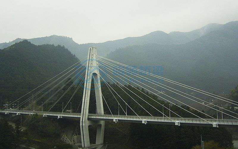
Cable-stayed bridge, also known as diagonal bridge, is a kind of bridge where the main beam is directly pulled on the bridge tower with many cables. It is a structural system composed of a pressurized tower, a strained cable and a bent beam body.

The cable-stayed bridge is mainly divided into three parts: main beam, cable tower and stay cable.
The main beam generally adopts concrete structure, steel-concrete combination structure,
Steel structure or steel and concrete mixed structure.
Cable tower -it adopts concrete, steel-concrete combination or steel structure. Most of them are concrete structures.
Stay cable - is made of high strength material (high strength steel wire or steel strand).
The load transfer path of the cable-stayed bridge is: the two ends of the cable-stayed cable are respectively anchored on the main beam and the cable tower, and the dead load and vehicle load of the main beam are transferred to the cable tower, and then transmitted to the foundation through the cable tower.
Therefore, the main beam is supported by the various points of the cable, and the continuous beam with multi-span elastic support is stressed, the internal bending moment of the beam is greatly reduced, and the size of the main beam is greatly reduced (the beam height is generally 1/50 ~ 1/200 of the span, or even smaller), which reduces the structural weight and greatly increases the crossing capacity of the bridge.

Span layout
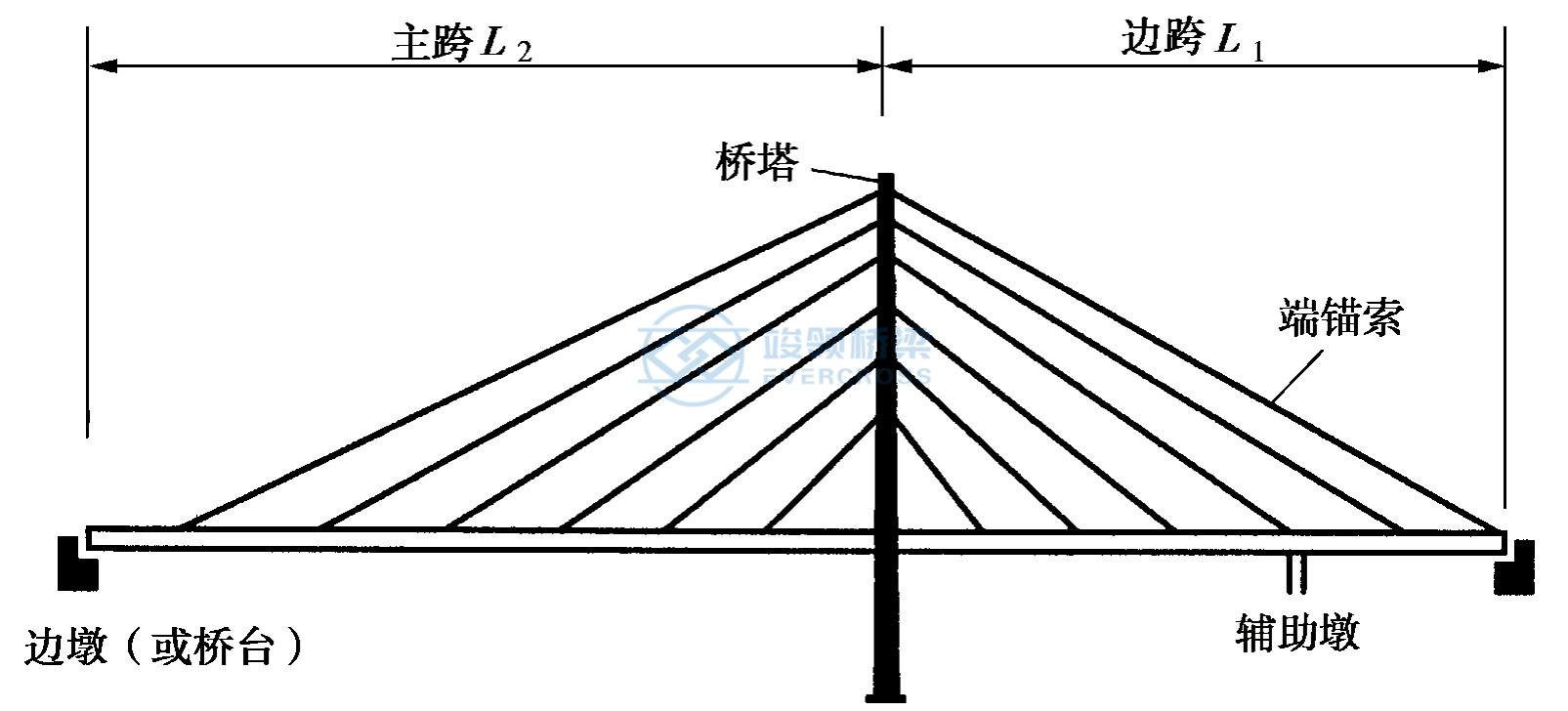
1. Twin tower three span: because of its main span is larger, generally suitable for crossing larger rivers.

2. Single tower double span: due to its main hole span is generally smaller than the main hole span of the twin tower three spans, it is suitable for crossing small and medium-sized rivers and urban channels.
3.Three-tower four-span and multi-tower multi-span: due to the middle tower top of the multi-tower multi-span cable-stayed bridge and suspension bridge has no end anchor cable to effectively limit its displacement, cable-stayed bridge or suspension bridge with flexible structure adopts multi-tower and multi-span will further increase the flexibility of the structure, which may lead to excessive deformation.

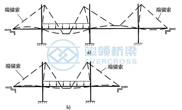
4. Auxiliary pier and side lead span

a) Guide span b) auxiliary pier
Live load often produces a large positive bending moment near the end of the side span beam, and leads to the rotation of the beam body, and the expansion joint is easy to be damaged. In this case, it can be solved by lengthening the side beam to form the lead span or setting the auxiliary pier. At the same time, setting the auxiliary pier can reduce the stress amplitude of the cable, improve the stiffness of the main span, and alleviate the negative reaction of the end fulcrum, which is a common method in long-span cable-stayed Bridges.
In addition, the installation of auxiliary piers is also convenient for the cantilever construction of cable-stayed bridge, that is, double cantilever construction to the auxiliary pier is equivalent to single cantilever construction, and its swing is small and safer.
Cable tower arrangement of cable-stayed bridge
The form of the cable tower
Cable tower is the main structure to express the personality and visual effect of cable-stayed bridge, so the aesthetic design of cable tower should be paid enough attention.
The tower design must be suitable for the arrangement of the cable, the force transmission should be simple and clear, and the tower should be under axial pressure as far as possible under the action of dead load.
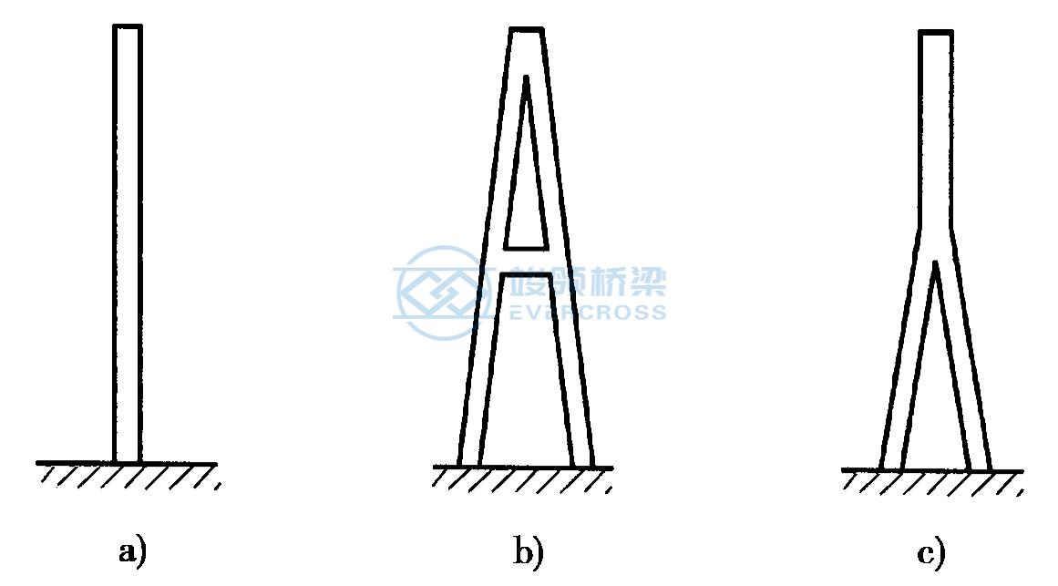
(a) It is single column type main tower, which is simple in structure.
(b) It is the A-shape.
(c) It is inverted Y type, which has high stiffness along the bridge and is conducive to withstand the unbalanced tension of the cable on both sides of the cable tower; The A-shape can also reduce the negative bending moment of the main beam at this point.
The layout of the cable tower cross bridge direction can be divided into single column type, double column type, door type or H type, A type, gem type or inverted Y type.
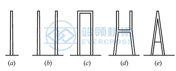
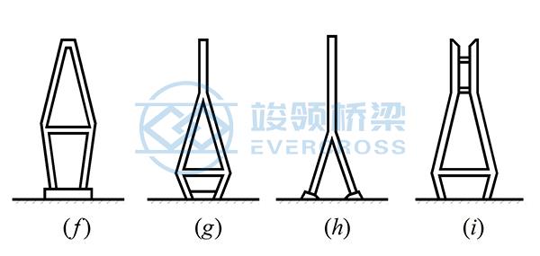
The vertical and horizontal arrangement of the pylon is single-column type, which is only suitable for single-plane cable-stayed Bridges. When it is necessary to strengthen the wind stiffness of the transverse bridge, the g or h type can be used. b~d is generally suitable for the case of biplanar cables; e, f, and i are generally suitable for cable-stayed bridges with double diagonal cable surfaces.
The height to span ratio of the tower
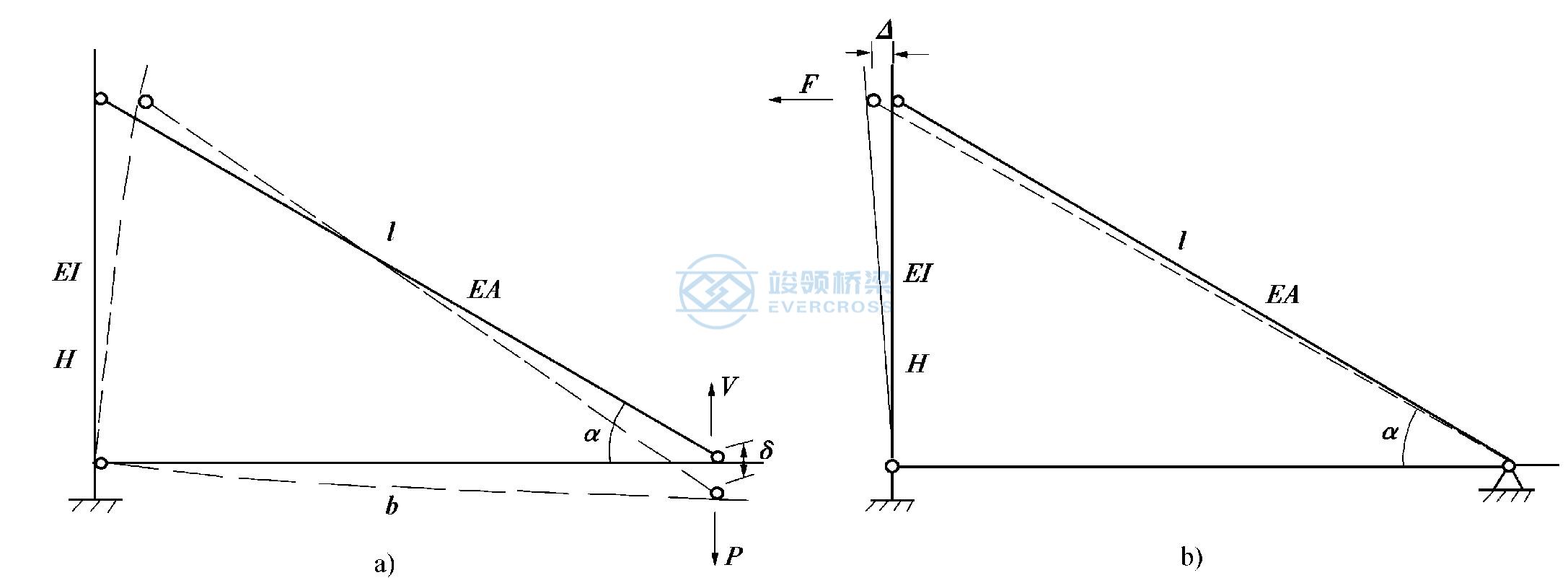
The height of the tower determines the stiffness and economy of the entire bridge.
Dragline arrangement
Cable-plane position
There are generally three types of cable surface positions, namely (a) single cable plane, (b) vertical double cable plane and (c) oblique double cable plane and multiple cable plane

Single cable plane: Box section with large mechanical torsional stiffness. The advantage is that from a perspective, the cable does not work against torsion. Therefore, the main beam should be used on the bridge floor with a wide field of view.
Vertical double cable plane: The torque acting on the bridge can be resisted by the axial force of the cable, and the main beam can use a section with lower torsional stiffness. Its wind resistance is relatively weak.
Diagonal double cable plane, which is particularly beneficial for the bridge deck beam body to resist wind torsional vibration (diagonal double cable plane limits the transverse swing of the main beam). Inclined double cable faces should adopt Y, A or twin pylons. If the span is too small, consider the view, should not be adopted. Generally, it is used when the span is greater than 600m, or when it cannot meet the requirements of wind resistance.
Cable-plane shape
There are three basic types of cable surface shapes as shown, namely (a) radial shape, (b) harp shape and (c) sector. Their respective characteristics are as follows:
Stay cable elevation layout
a)radiative shape. b) Harp shape. c) Sector.

(a) The radial arrangement of the cable is evenly distributed along the main beam, while on the tower it is concentrated at the top point. Because the average intersection angle between the cable and the horizontal plane is large, the vertical component of the cable has a large supporting effect on the main beam, but the structure of the anchorage point on the top of the tower is complicated.
b) The cable in the harp-shaped arrangement is arranged in parallel, which is more concise when the number of cables is small, and can simplify the connection structure of the cable and the cable tower. The anchorage points on the tower are scattered, which is beneficial to the force of the cable tower. The disadvantage is that the inclination angle of the cable is small, the total tension of the cable is large, so the cable is used more.
(c) The sector arrangement of the cable is not parallel to each other, it has the advantages of the above two arrangements, and has been widely used in design.
Layout of cable spacing
The arrangement of cable distance can be divided into "thin cable" and "dense cable".
Early stage - thin cable. Modern – dense cable (Computer Computing)
The advantages of the dense cable system are as follows:
1. The cable distance is small, the main beam bending moment is small (the cable distance on the main beam is generally 4-10m concrete beam, steel beam is 12-20m);
2. The cable force is small, the anchoring point structure is simple;
3. The change of stress flow near the anchoring point is small, and the reinforcement range is small;
4. Conducive to arm erection;
5. Easy to change cable.
6. When the cable-stayed bridge is erected by cantilever method, the cable spacing should be 5 ~ 15m.
The structural system of cable-stayed bridges can be divided into the following different ways:
according to the combination of tower, beam and pier: Floating system, semi-floating system, tower beam consolidation system and rigid structure system.
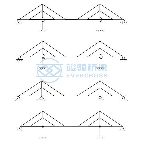
According to the continuous mode of the main beam, there are continuous system and T-structure system.
According to the anchoring method of the cable, it is classified as self-anchoring and ground anchoring
Most cable-stayed Bridges are self-anchored systems. Only when the main span is large and the side span is small, a few cable-stayed bridges use partial ground anchor system.
Low tower partial cable-stayed bridge system
Classification by tower height: conventional cable-stayed bridges and partial cable-stayed bridges with low towers.

The mechanical performance of the low-pylon partial cable-stayed bridge is between the beam bridge and the cable-stayed bridge.
The structure of the main beam of the cable-stayed bridge
The function of the main beam has three aspects:
(1) Distribute the dead load and live load to the cable. The smaller the stiffness of the beam, the smaller the bending moment.
(2) As part of the whole bridge together with the cable and tower, the force borne by the main beam is mainly the axial pressure formed by the horizontal component of the cable, so it needs to have sufficient stiffness to prevent buckling;
(3) Resist transverse wind and seismic loads and transmit these forces to the substructure.
When the cable distance is large, the main beam is designed by the bending moment control. For single-cable plane cable-stayed bridges, the main beams are designed by torsion control. For the double cable system, the main beam design should mainly consider the axial pressure factor and the longitudinal bending of the whole bridge.
In addition, it should be considered that the main beam has sufficient strength and stiffness to replace the cable with a reduced live load. It is also necessary to consider that the structure still has enough safety reserve when the individual cable breaks or exits the work accidentally.
Suitable span of main beams of different materials
The main beams of cable-stayed bridges are composed of four different ways:
1.Prestressed concrete beams, known as concrete cable-stayed bridges, economic span less than 400m.
2.Steel-concrete composite beam, called composite beam cable-stayed bridge, economic span 400 ~ 600m.
3. All steel main beam, known as steel cable-stayed bridge, economic span more than 600m.
4. The main span is a steel main beam or a steel-concrete composite beam, and the side span is a concrete beam, which is called a hybrid cable-stayed bridge with an economic span of more than 600m.
Cable tower of the cable-stayed bridge
The composition of the cable tower components: the tower plays a decisive role in aesthetics: careful selection of shapes, drawing size proportions, using models, and local optimization.
The main component of the cable tower is the tower column, and there are also beams or other connecting members between the tower columns.
Generally, the beams between the tower columns can be divided into load-bearing beams and non-load-bearing beams. The former is a bending beam for setting the support of the main beam, and a pressure rod beam or a tie rod beam at the bend of the tower column. The latter is the top beam of the tower and the middle beam of the tower column without turning.
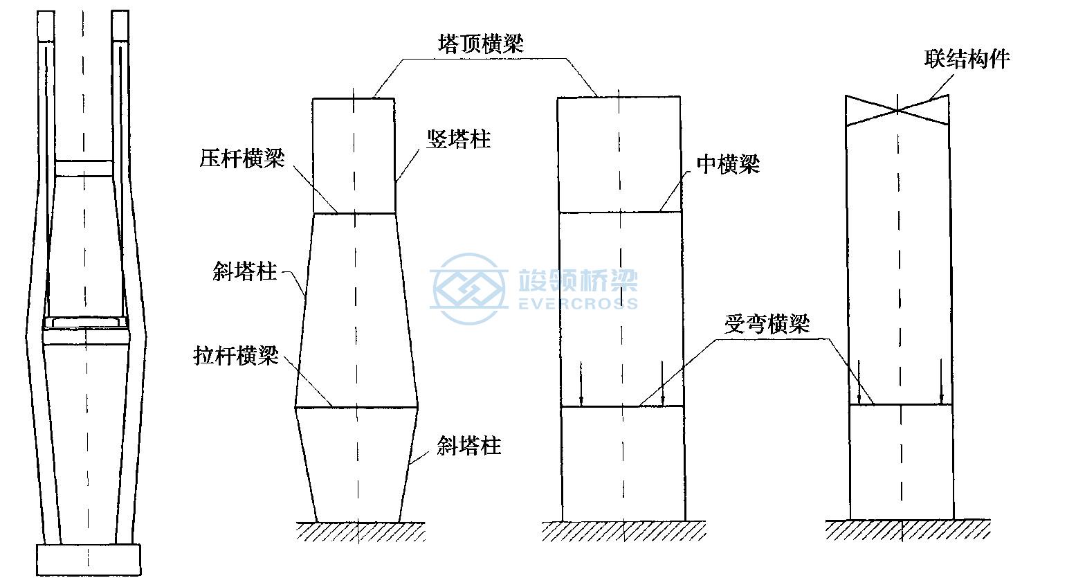
The structure of the concrete tower
Generally, solid body cable tower is suitable for small and medium span cable-stayed bridge, for small span can be used equal section, for more than medium span cable-stayed bridge column can be used hollow section.
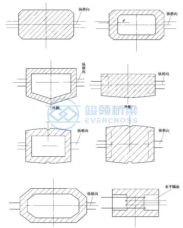
The structure of the rectangular section cable tower is simple, and its four corners should be made of chamfer or rounded corners to facilitate wind resistance. The H-section pylon is the most unfavorable against the wind. Octagonal section is conducive to the configuration of closed circumferential prestressed tendons, but the structure is slightly complicated.
The H-shaped section on the facade can not expose the anchor head, which improves the appearance, but at the same time creates four cable planes.
This problem can be solved by using H-section towers with two cable planes. However, using one form will cause the bridge tower to be twisted, and using two forms to cross the upper and lower settings can avoid the bridge tower to be twisted but not beautiful.
Guy cable of the cable-stayed bridge
The construction of guy cable
The structure of dragline is basically divided into two categories: integral installation cable and dispersed installation cable. The representation of former is parallel wire cables with cold-cast anchors, while the representation of the latter is parallel wire cables with clip anchors.
1.Parallel wire cable with cold cast anchor

2.Parallel steel cable with clip anchor
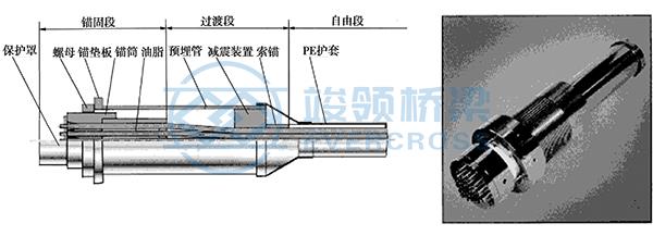
The steel wire in the parallel wire cable is replaced by a steel strand of equal section, which becomes a steel strand cable.
Single steel strand cable weight is light, transport and installation is convenient, but the anchor head needs on-site protection, quality assurance difficulty increases.
Anchorage of the cable
1. Anchorage of the cable on the beam
The vertical component is balanced by the stiffening oblique bar.
2. Anchoring of the cable on the cable tower
Damping of the cable
The wind-induced vibration of the cable is common in all kinds of span and types of cable-stayed bridges, and the vibration of the cable is easy to cause fatigue and damage. At present, the main measures to reduce the vibration of the cable of the cable-stayed bridge are as follows:
(1) Pneumatic control method
(2) damping vibration reduction method
(3) Changing the dynamic characteristics of the cable
1. Pneumatic control method
The original smooth surface of the cable is made into a non-smooth surface with spiral ridges, bar ridges, V-shaped grooves or circular concave points. The bump on the cable surface can prevent the formation of the cable waterline when it rains, thus preventing the occurrence of rain vibration.
2. Damping vibration reduction method
The mechanism of damping vibration reduction method is to increase the damping ratio of the cable by installing damping device so as to restrain the vibration of the cable. According to the relationship between the damping device and the cable, the damping device can be divided into an internal damper placed in the sleeve and an external damper attached to the cable.
3. Method of changing cable dynamic characteristics
Several cables are connected to each other by couplings (cable clamps) or auxiliary cables, which may be of a much smaller diameter than the main cable.
The mechanism of action is that the long cable is converted into a relatively short cable through the connection, so that the vibration base frequency of the cable is increased, and the vibration of the cable is suppressed.
It is very effective to prevent low frequency vibration, and can also reduce the probability of rain vibration and single cable vibration, but the suppression of vorticity vibration usually occurs in the form of high order is not obvious. In addition, the auxiliary cable is prone to fatigue fracture, which has a certain impact on the bridge landscape.
The construction method of cable-stayed bridge can be summarized as follows: there are support construction method, push construction method, rotary construction method and cantilever construction method (cantilever assembly and cantilever pouring).
Application of cable-stayed bridges: highway cable-stayed bridge, railway cable-stayed bridge
The advantages of cable-stayed bridges:
The size of the beam body is small, and the crossing capacity of the bridge is large.
Less restricted by the bridge clearance and deck elevation.
The wind stability is better than suspension bridge.
There is no need for centralized anchorage structure like suspension bridge.
Easy to cantilever construction.
|
EVERCROSS STEEL BRIDGE SPECIFICATION |
|
|
EVERCROSS STEEL BRIDGE |
Bailey bridge (Compact-200, Compact-100, LSB, PB100, China-321, BSB) |
|
DESIGN SPANS |
10M TO 300M Single span |
|
CARRIAGE WAY |
SINGLE LANE, DOUBLE LANES, MULTILANE, WALKWAY, ETC |
|
LOADING CAPACITY |
AASHTO HL93.HS15-44, HS20-44, HS25-44, |
|
STEEL GRADE |
EN10025 S355JR S355J0/EN10219 S460J0/EN10113 S460N/BS4360 Grade 55C |
|
CERTIFICATES |
ISO9001, ISO14001, ISO45001, EN1090, CIDB, COC, PVOC, SONCAP, etc. |
|
WELDING |
AWS D1.1/AWS D1.5 |
|
BOLTS |
ISO898, AS/NZS1252, BS3692 or equivalent |
|
GALVANIZATION CODE |
ISO1461 |


 Certified

