Composite Beam Bridge

Composite beam bridge, it refers to a composite structural beam bridge which combines steel members such as steel plate beams, steel box beams, steel truss beams and reinforced concrete members to work together by using shear connectors.
In the past, simply-supported beam bridge was the most used, but in recent years, it has been extended to continuous beam bridge, cable-stayed bridge, suspension bridge, tied arch bridge and other complex systems.
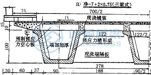
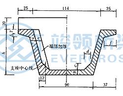
The composite beam bridge is also a kind of assembled bridge span structure, which separates the beam rib part of the bridge from the bridge panel (wing plate) through the longitudinal horizontal joint, so that the overall section of the single beam becomes the combined section of the plate and the rib. During construction, beam ribs are first erected, prefabricated panels are installed (sometimes with slightly bent panels to save steel bars), and finally a portion of concrete is cast in place within the joints or along with the panels to make the structure a whole. Therefore, the composite beams are stressed in stages. After the beams are erected, the weight of all the prefabricated panels and cast-in-place deck concrete (and even the cast-in-place cross spacer beams) installed subsequently, together with the weight of the beams themselves, must be borne by the prefabricated beams. This is different from the assembled T-beam to bear all the dead load by the full section of the main beam, the bending inertia moment of the rib without the wing plate is much smaller than the whole T-beam (the rib height is lower, the neutral axis is moved down, the internal couple arm is small, and the compression concrete is insufficient), which will inevitably greatly increase the burden of the beam rib to bear all the structural dead load, so not only to increase the cross-section of the beam rib, but also to increase the reinforcement. The increase of the amount of concrete in beam ribs leads to the unfavorable increase of dead load. Below picture shows the comparison of stress graphs between the prefabricated T-beam and the composite beam at two stages: permanent action Mg and variable action Mp.
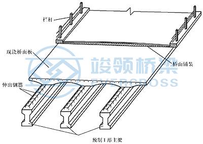

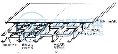
According to the materials used in the plates and ribs of the composite beams, the composite beams are divided into concrete composite beams and steel-concrete composite beams. The composite concrete beams are integrated by casting concrete in situ in the joints or together with the precast slab of the bridge floor. Steel-concrete composite beams are made of steel beams in the beam ribs and reinforced concrete slabs in the bridge panels, which are combined with each other through shear keys (also known as connectors) to participate in the structural force.
2. Structural characteristics of composite beam bridge
The section is a combination section.
The section stiffness increases to reduce the quantity of steel.
Under the action of live load, the noise is less than that of all steel beam bridge.
Easy to adjust slope and external superelevation.
In order to ensure the joint force of steel beam and reinforced concrete road slab, a reliable shear transfer device must be set up to transfer the staggered shear force of the beam in bending deformation.
Rigid shear transfer.
Adopt short section steel, such as channel steel, angle steel.
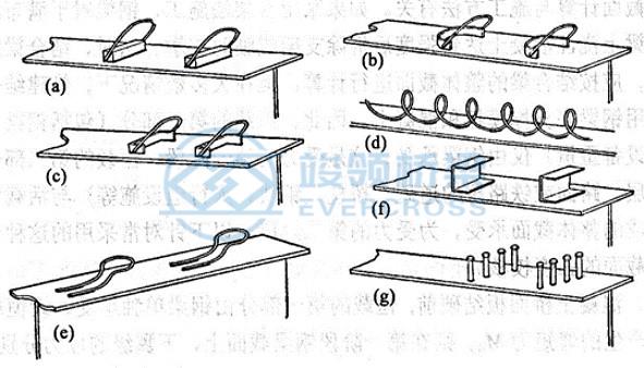
Flexible shear transfer
Diagonal reinforcement, if reliable, can also be used in other forms such as capped bolts.
The shear transfer shall be welded to the upper flange of the steel beam and welded to the steel bar of the bridge panel.
The structural form of composite structure bridge:
Composite plate girder bridge
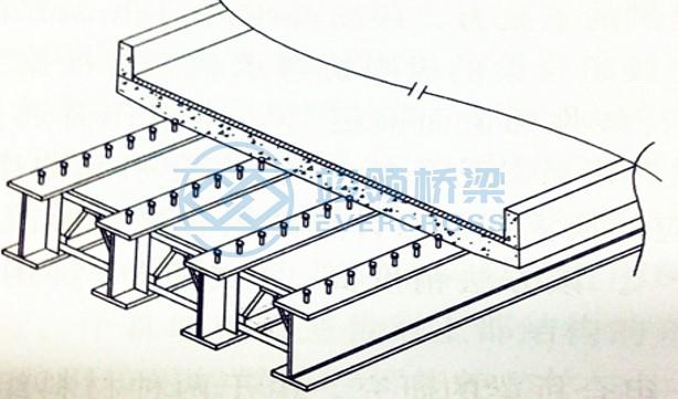
For medium and small span composite girder Bridges, in order to reduce the production and installation costs, it usually use steel beams with I-section which also known as composite plate girder bridges.
The steel beams of composite plate girder bridges can be made of rolled section steel or welded steel beams.
It can adopt an asymmetric steel beam section to reduce the size of the upper steel beam flange attached to the concrete bridge panel.
Composite box girder bridge
The box-type composite beam bridge has higher torsional rigidity and more stability than the I-section composite bridge.
Increase the crossing capacity, solve the problem of insufficient clearance under the bridge and avoid the interruption of traffic during construction;
Before concreting the bridge floor, concrete can be poured over the steel box girder bottom plate in the negative bending moment zone, which can not only play the role of compressive resistance, but also improve the stability of the steel box girder bottom plate and web plate.
Composite truss bridge
Steel truss is used instead of solid steel beam and combined with concrete bridge panel.
It has better permeability and aesthetics;
The beam height is usually larger than that of the solid belly beam bridge, and the design of the joint is more complicated, especially the high requirement for the construction of the joint connecting the bridge panel and the web plate.
Composite rigid frame bridge
Steel-concrete composite beams are consolidated with concrete piers or composite piers. Reduce the load of bridge floor system and reduce the use of support;
Large headroom under the bridge, beautiful shape, good smoothness of the bridge floor. Compared with the simple supported beam bridge, its seismic performance is higher, and no falling beam accidents will occur.
The key problem to be solved in the design and construction is to ensure that the load of the bridge floor can be effectively transferred to the pier namely the structure of the beam-squat joint.
Steel-concrete composite beam bridge is a new type of bridge structure developed on the basis of steel structure beam bridge and concrete structure beam bridge. The main components such as beam ribs usually adopt steel structure, the bridge panel or flange plate adopt concrete structure, and the shear connector between steel and concrete adopt shear connectors to a whole, to make the two structures are jointly stressed. The combination of the two materials can avoid their respective shortcomings, give full play to the advantages of the two materials, and form a structural form with high strength, high stiffness and good ductility. Compared with the simple concrete beam, it can reduce the section size of the component and the dead load of the structure can be reduced and alleviated the earthquake action.
Compared with the simple steel beam, it can reduce the use of the amount of steel, save the painting cost of the steel structure, reduce the noise pollution of the steel bridge, and increase the stiffness, stability and integrity of the structure.
Steel beams are mainly subjected to tension in composite beams. For small and medium span steel-concrete composite beam bridges, steel plates are generally welded into I-shaped (I-shaped) steel beams. In order to give full play to the role of steel, I-shaped steel beams often use asymmetric cross sections with wide lower flanges. For steel-concrete composite beam bridges with large span, the cross-section form of closed or open steel box girder is mostly used, so it is also called box composite beam. Box-shaped composite beams have high torsional stiffness, which is especially suitable for curved bridges, and most of them are designed as continuous structures in the direction of the bridge.
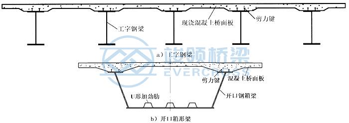
Reinforced concrete bridge panels supported by steel beams, in addition to the longitudinal bending moment shared by the upper flange of the composite beam and the steel beam. It also bears the internal forces in the direction of the cross bridge caused by local loads as the bridge panel. The bridge panel usually adopt two forms of cast-in-place concrete slabs and precast concrete slabs, and the bottom surface of the bridge panel can be designed in a straight or curved shape.

The shear key on the top surface of the flange plate on the steel beam is the basis for the joint operation of the steel beam and the concrete bridge panel. The main function of the shear bond is to withstand the longitudinal shear force on the interface between the steel beam and the concrete bridge panel, and resist the relative slip. There are many kinds of shear keys used in composite beams. In the current "Code for Design of Highway Steel Structure Bridges" (JTG D64), welded nail shear keys, channel steel shear keys and perforated plate connectors are adopted, as shown below, among which welded nail shear keys are the most widely used.

Calculation characteristics of composite beams
Scaffold construction: The overall section of the superimposed beam bears all the loads, and the section stress should be calculated according to the overall section of the superimposed beam.
Direct use of steel beams to support formwork and concrete.
In the first stage, the first part of the dead load (including steel beams, formwork, concrete and their construction equipment weight) is borne only by steel beams.
In the second stage, the second part of the dead load (including the bridge deck pavement layer, waterproof layer, road surface) and the live load are borne by the overall section composed of reinforced concrete slabs and steel beams, and finally superimposed to check the strength of the composite beam section.
Application of composite beam bridge: Highway bridge and railway bridge
Advantages of composite beam bridge
Convenient for construction. Because of the strength of steel rod, light weight, easy to set up.
Alleviate the dead load. Compared with concrete bridges, the dead load is light, which is especially important for long-span beam Bridges, which can reduce the proportion of dead load and reduce the requirements on the lower structure and foundation.
Improve performance. By steel tensile, concrete compressive, give full play to the performance of the material. When concrete filled steel tube is used, the hoop effect of steel tube on concrete can be used.
Save cost. In long-span Bridges, it is a little more obvious.
Evercross Steel Bridges Overview:
EVERCROSS STEEL BRIDGE SPECIFICATION | |
EVERCROSS STEEL BRIDGE | Bailey bridge (Compact-200, Compact-100, LSB, PB100, China-321, BSB) |
DESIGN SPANS | 10M TO 300M Single span |
CARRIAGE WAY | SINGLE LANE, DOUBLE LANES, MULTILANE, WALKWAY, ETC |
LOADING CAPACITY | AASHTO HL93.HS15-44, HS20-44, HS25-44, |
STEEL GRADE | EN10025 S355JR S355J0/EN10219 S460J0/EN10113 S460N/BS4360 Grade 55C |
CERTIFICATES | ISO9001, ISO14001, ISO45001, EN1090, CIDB, COC, PVOC, SONCAP, etc. |
WELDING | AWS D1.1/AWS D1.5 |
BOLTS | ISO898, AS/NZS1252, BS3692 or equivalent |
GALVANIZATION CODE | ISO1461 |


 Certified


